Using Custom Flowlets
Encapsulate ad-hoc or chained logic or conditions for your site or app
As discussed in the API Overview, the Conductrics Runtime API allows you to execute commands to Get Selections from Agents, and to Send Rewards back to those agents as Goals are achieved.
Sometimes you may want to create additional "custom logic" that can be executed via the API.
For instance, perhaps you want to:
- Create some kind of "custom logic" or that chains together a sequence of Selections and Rewards, triggering several different agent selections along the way.
- Or you may want to create some kind of "custom conditions", perhaps to filter certain visitors in or out of an A/B test you are running.
- Or you may want to return custom information back to your site or app along with any agent selections.
Situations like the above are where Flowlets come in. They allow you to arrange agent selections, rewards, custom conditions, and other bits of functionality into a visual "diagram" that looks somewhat like a flowchart or decision tree. You can "call" the Flowlet via the API, kind of like calling a function or "macro".
Create a Flowlet
The first step is to create a new Flowlet.
- Go to Developers > API Flowlets in the Conductrics Admin.
- Click the New Flowlet button and provide a name for the Flowlet, such as Flowlet 1 or Home Page Flowlet.
- Click Create.43

Creating a new Flowlet.
Now click the View / Edit link for the new Flowlet. You'll be taken to its diagram-editing page as shown below.
At first there isn't much to see, because the main part of the page shows the "diagram" for the Flowlet, which at this point is still empty.
Here's what a new, empty Flowlet looks like before you drag in any custom "logic".
Adding "Diagram Nodes" to the Flowlet
To make the Flowlet actually do something, you'll add diagram nodes to it. For example:
- Click Edit Flowlet at top right, which puts the Flowlet into "editing" mode. You'll note that a "palette" of draggable items appears on the right.
- Drag the Get Selection item from the palette into the diagram, dropping it on the Flowlet's root node (labelled Flowlet 1 in the example screenshot above).
- When you drop the item, it becomes a new Get Selection node in the diagram as shown above. The node is shown in red because more information is needed to complete it.
- Click the red Get Selection label to get to the editing window for the node.
- Complete the required information, which will vary depending on the type of node you added. In this case all that's needed is to choose an Agent so the system knows which agent to get a selection from when the node is processed.

You provide or edit details for a given node here. The fields available will be different for different types of nodes.
When you click OK, the system may automatically add some appropriate child nodes. In this case, a simple agent that chooses between "Variation A" and "Variation B" was selected, so the system adds "If Selected" nodes for each of the potential selections.
Executing Your Flowlet
You can call your Flowlet via the Runtime API. One way to get started is to use The API Testbed:
- Get to the Testbed via Developers > API Testbed in the Conductrics Admin.
- Select your Flowlet from the dropdown provided and click Add to add it to the Commands to Run area. You'll note that the Flowlet's "task code" (visible in the visual diagram in the screenshots above) is specified in the command.
- Click Run Commands.

Conditions for Your Diagram Nodes
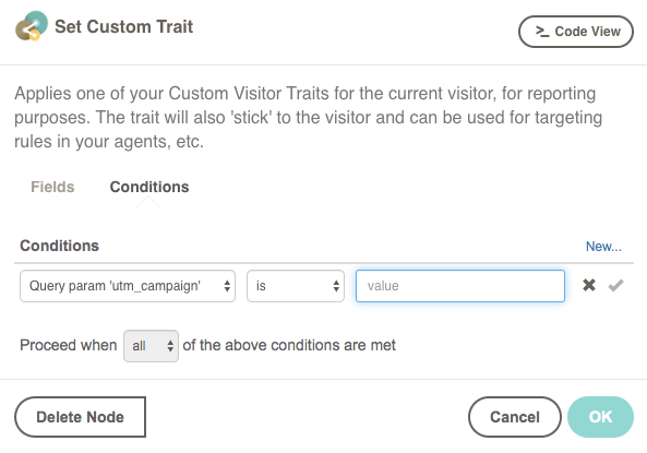
Nearly all types of diagram nodes will accept custom conditions, which you supply in the Conditions tab of the editing window for the node.
- Use the Edit Flowlet button at top right to enter editing mode.
- In the diagram, click on the name of the node you want to change. The node's edit window appears, shown below.
- In the Conditions tab, click Add Condition and use the dropdowns to create the conditions you need.
When the Flowlet actually executes at runtime, your conditions will be evaluated when the system reaches the node in question. If the conditions pass, the node and its children will be processed. If the conditions do not pass, the node and its children will be skipped.
Deleting Diagram Nodes
If you need to delete a diagram node from your flowlet:
- Click Edit Flowlet at top right to enter edit mode.
- Click on the name of the node you want to remove.
- In the node-editing window that appears, click Delete Node and confirm. The node will disappear from the diagram. All of its children will be gone too.
- The deletion isn't permanent until you save your work via the Save button at top right.
Or, to delete the whole Flowlet, return to the the API page and remove the Flowlet from there.
Updated over 1 year ago